
Defects in metal welding are often hidden in details. Most welding failures are not caused by equipment issues, but by human operational errors. This article focuses on the 5 most common mistakes in metal welding, combined with practical solutions, to help welders avoid defects, improve welding quality, and provide a more efficient optimization direction for industrial scenarios.
Quick Overview Table of 5 Common Metal Welding Mistakes
|
Mistake Type |
Core Cause |
Quick Solution |
|
Inadequate Base Metal Surface Preparation |
Residues of oil, rust, and oxide layers |
Thoroughly clean with acetone, wire brush, and special abrasive tools before welding |
|
Incorrect Welding Parameter Settings |
Mismatched voltage, current, and wire feed speed |
Calibrate with test welding on scrap metal; use multi-layer welding for thick plates |
|
Unstable Travel Speed |
Excessively fast/slow speed leading to insufficient penetration or burn-through |
Use guide rails to maintain uniform speed and heat input |
|
Improper Welding Torch Angle |
Too steep/shallow angle affecting fusion |
Maintain a standard angle of 10–15° from the vertical direction |
|
Abnormal Shielding Gas Flow |
Insufficient/excessive flow causing porosity and oxidation |
Set 15–40 CFH for MIG/TIG according to material; wind protection for outdoor use |
The above 5 types of mistakes are the most common and preventable in metal welding, covering core links such as surface preparation, parameter setting, and operation techniques. Standardizing each step of the operation can directly reduce more than 80% of welding defects and improve weld strength and consistency.
5 Must-Avoid Mistakes in Metal Welding
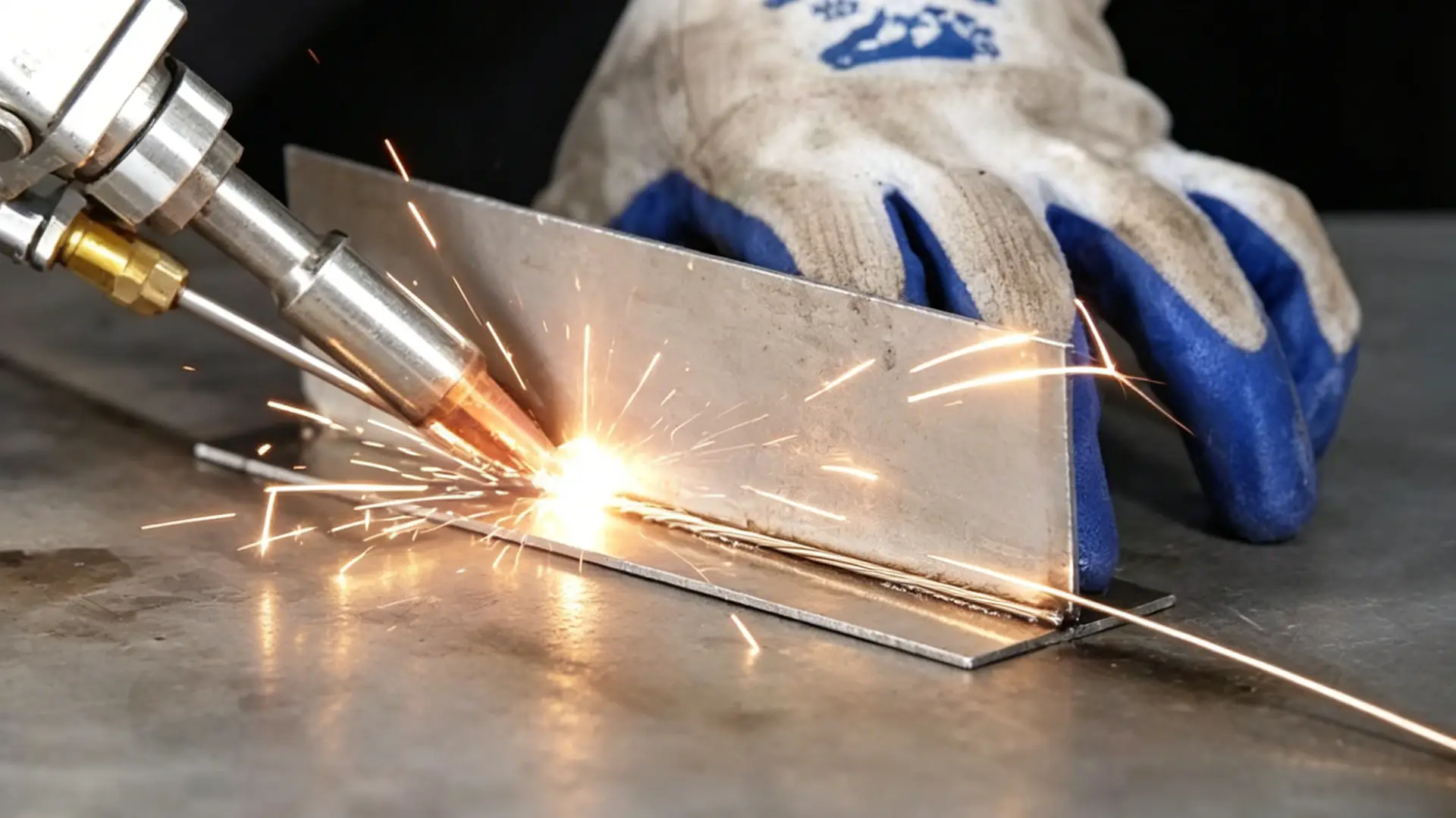
1. Ignoring Base Metal Surface Preparation
Surface contamination is the primary cause of welding failure, with approximately 40% of welding defects resulting from residues of oil, rust, and oxide layers. Impurities can cause porosity, hydrogen-induced cracks, and lack of fusion, significantly reducing joint strength.
– Carbon steel: Degrease → sandblasting/grinding, use acetone + wire brush; – Stainless steel: Solvent degreasing → treatment with special stainless steel brush/nylon pad; – Aluminum: Alkaline etching → desmutting, use phosphoric acid dipping + fine sandpaper. Fully dry after cleaning to avoid moisture residue. Standardized pre-treatment can triple adhesion and reduce rework rate by 50%, which is the basic link to stabilize welding quality.
2. Randomly Setting Welding Parameters Based on Experience
Mismatched parameters directly lead to insufficient penetration, burn-through, and excessive spatter. Voltage controls arc length, and wire feed speed determines current; both need to be coordinated to match the plate thickness.
– Thin plate (1/16″–1/8″): 16–19V, 80–150 IPM, 70–110A; – Medium plate (1/8″–1/4″): 19–22V, 150–250 IPM, 110–180A; – Thick plate (1/4″–1/2″): 22–26V, 250–350 IPM, 180–250A. Unified operation: Perform 4–6 inch weld test on scrap metal of the same material and thickness, observe the molten pool and weld formation, adjust voltage first and then match wire feed speed, and reduce heat input by 10% for vertical welding.
3. Fluctuating Travel Speed
Excessively fast speed tends to cause narrow and convex welds, porosity, and poor fusion; excessively slow speed leads to excessive heat accumulation, causing burn-through, deformation, and deterioration of heat-affected zone performance.
Practical points: – Use guide rails to ensure straight and uniform travel; – Use intermittent welding for thin plates to control cumulative heat input; – Symmetrical tack welding to balance shrinkage stress and reduce deformation. Stable speed + reasonable temperature control can significantly improve weld uniformity and structural stability.
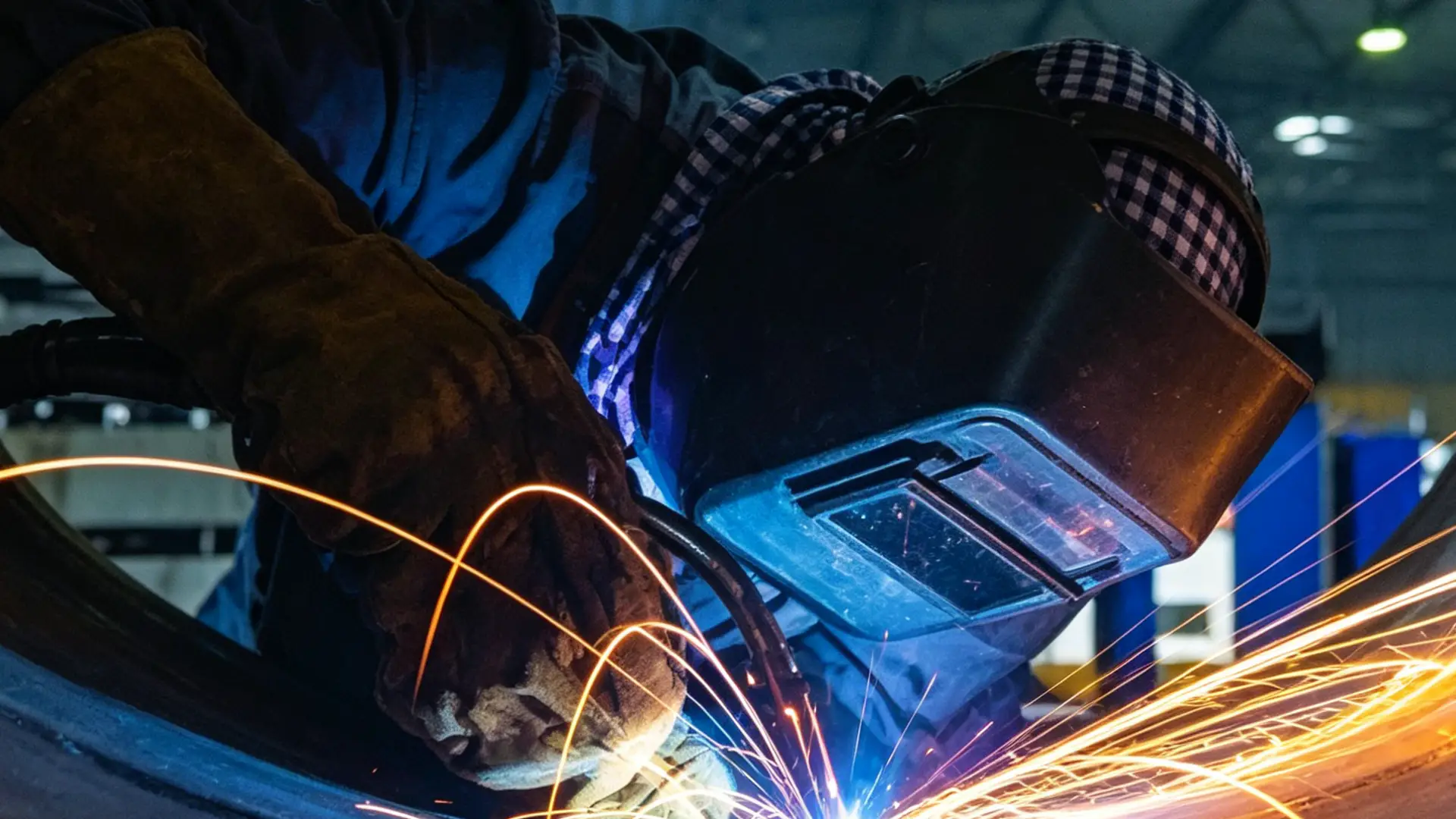
4. Incorrect Welding Torch Angle and Push/Pull Technique
Angle deviation directly reduces the fusion rate: the correct angle can reach 90% fusion, while the wrong angle is only about 60%.
– Butt welding: 0–15° drag angle; – T-joint welding: 45° aligned with the vertical leg, 10–20° drag on the horizontal; – Corner welding: 30–45° forehand (push) welding to ensure sidewall fusion. Technique specifications: 15–20° drag angle is mostly used for MIG welding of steel; 10–20° forehand welding is used for aluminum and thin plates. Check the angle every 6 inches of travel; exceeding 25° will double the risk of undercutting.
5. Improper Control of Shielding Gas Flow
Insufficient flow is prone to oxidation and dense porosity; excessive flow is prone to turbulence that draws in air, also causing defects.
Standard flow reference: – MIG carbon steel: 20–30 CFH; stainless steel: 25–35 CFH; aluminum: 30–40 CFH; – TIG carbon steel: 15–20 CFH; stainless steel: 20–25 CFH; aluminum: 25–35 CFH. For outdoor operations, install windshields, appropriately increase the flow by 20–50%, shorten the nozzle distance, and keep the welding torch vertical. Continue gas supply for 5–10 seconds after extinguishing the arc to protect the molten pool from end oxidation.
Pain Points of Traditional Welding and Optimization Scheme of Laser Welding
Traditional welding relies heavily on manual operation, and the above 5 types of mistakes occur frequently, leading to high defect rates, high rework costs, difficult deformation control, and poor consistency. Even skilled welders are prone to process errors due to solidified habits, making it difficult to meet the high-precision and high-stability requirements of industrial welding.
Laser welding uses a high-energy density beam as the heat source, avoiding manual operation errors from the process level: – Extremely narrow heat-affected zone, small base metal deformation, greatly reducing the risk of distortion; – Non-contact processing, no need for complex surface pre-treatment, reducing defects caused by contamination; – Precise and controllable energy, stable penetration, no spatter, few pores, and uniform weld formation; – Strong automation adaptability, one-click parameter locking, avoiding manual setting fluctuations; – Fast welding speed, improved efficiency, no need for multi-layer and multi-pass welding, reducing the probability of speed and angle errors.
Laser welding can effectively solve defects caused by surface preparation, parameters, speed, angle, and gas flow, significantly improve welding qualification rate and structural strength, adapt to various metal precision welding scenarios such as carbon steel, stainless steel, and aluminum, and is the preferred path for improving quality and efficiency in industrial welding.
Conclusion
The core of superior metal welding quality is to avoid five common errors: improper surface treatment, incorrect parameter settings, unstable travel speed, wrong welding torch angles and unreasonable gas flow control. Standardized workflows can greatly reduce defects including porosity, incomplete fusion, deformation and cracking, while enhancing the overall strength and stability of welded joints.
It is difficult to eliminate operational errors completely with traditional manual welding methods. In contrast, laser welding stands out as an ideal solution for industrial upgrading and efficiency improvement, thanks to its high precision, low heat impact and outstanding consistency. It minimizes human-induced errors through optimized craftsmanship and ensures long-term stable and reliable welding results.
With 15 years of expertise in the laser industry, Maxwave specializes in intelligent laser equipment including laser welding machines, laser cleaning machines and laser marking machines. We support customized solutions and automated system integration. Our equipment is stable, safe and fully compliant with international standards, effectively solving common metal welding defects. We help manufacturers boost welding quality, cut rework costs and achieve consistent mass production. If you need reliable high-precision metal welding solutions, feel free to contact Maxwave for a tailored professional plan.