
Picking the wrong laser welder for mold repair hurts more than your budget. You lose jobs, damage your reputation, and burn months on rework.
Most buyers walk in with just a spec sheet and a sales pitch. That’s not enough.How to choose the right laser welder for mold repair comes down to a few critical parameters: peak power, pulse width, spot diameter, and steel compatibility. Each one directly affects your results on P20, H13, or S136 tool steel.
Here’s an engineer-level framework to compare machines. No fluff. No definitions. Just what matters.
Why Laser Welding for Mold Repair
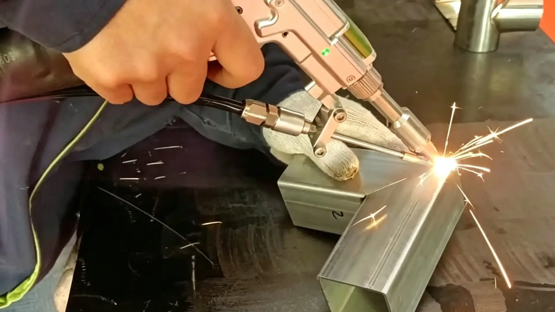
Heat is the enemy of mold repair. Laser welding puts in less heat than any other fusion process. The heat-affected zone stays tiny. Distortion risk drops to almost zero.
With laser, you can place a weld within a few thousandths of an inch of a parting line or a detailed cavity wall. TIG can’t do that.
Results add up fast: fine-grain weld metal, no undercut, little to no discoloration, no preheat needed for most mold steels. U.S. mold shops logged more than 3,500 successful laser repairs over five years. Today’s systems produce beads as small as 0.05 mm.
Step 1: Define Your Mold Repair Use Case
Before you compare specs, answer one question: what are you repairing, and how often?
A 50W precision mold repair machine and a 1,500W continuous laser welder are built for completely different jobs.
By mold type:
-
Injection molds (P20, H13, NAK80, S136): Most repairs cover parting line touchups and gate wear. Weld widths run 0.2–1.0 mm. You need fine spot control, not raw power.
-
Die casting molds (H13, 8407): Cavity erosion and heat-check cracking need deeper penetration – 200–500W pulsed or 1–2kW continuous output.
-
Stamping dies (D2, Cr12MoV): Chipped cutting edges call for ultra-fine spots (0.2–0.5mm) and very low heat input.
The practical rule: More than 70% of your annual repair volume is micro-precision work? A high-power machine won’t help – it’ll get in your way.
Step 2: Choose Fiber Laser Over Nd:YAG
Two technologies dominate. One is aging fast.
Efficiency: Lamp-pumped Nd:YAG converts just 2–3% of input electricity into laser output. Fiber lasers run at 28% or higher. To deliver 200W output, YAG pulls 6.7 kW from the wall. Fiber draws 0.67 kW.
Maintenance: YAG lamps need replacement every 400–800 hours. Each swap costs 2–4 hours of downtime. Fiber lasers have no lamps, no optical cavities to recoat, and a rated service life of 100,000 hours.
Beam stability: Lamp-pumped YAG suffers from thermal lensing. Beam focus shifts during long sessions. Fiber lasers hold power stability within ±1–2% over an 8-hour shift.
The bottom line: For most mold repair environments, fiber laser is the correct choice. Lower operating cost, better beam quality, stable output. The maintenance savings alone cover the price premium within the first two years.
Step 3: Know the Power & Pulse Parameters
Three numbers run the show: peak power, pulse width, and pulse frequency.
Pulse energy (J) = Peak power (W) × Pulse width (s)
Average power (W) = Pulse energy × Frequency (Hz)
How each parameter controls the weld:
-
Pulse energy drives penetration depth. On H13 at 0.5mm spot diameter: 1–1.5 J gives 0.2–0.3mm depth. 3–4 J gives 0.6–0.8mm depth.
-
Peak power shapes the bead profile. 1 kW / 3ms gives wider, shallower beads. 3 kW / 1ms gives narrower, deeper beads.
-
Average power controls total heat buildup. Under 50W is safe for S136 and hardened H13. 50–150W is standard for P20 cavity repairs.
Steel-specific windows:
-
H13 (48–52 HRC): Preheat to 250–350°C. Run 10–30 Hz at 3–6ms pulse width. Keep energy at 0.8–2J per pulse.
-
P20 (28–32 HRC): Preheat to 150–250°C. 20–80 Hz at 0.8–2.5J for micro repairs.
-
S136 (48–52 HRC mirror steel): Preheat to 200–300°C. Run 10–25 Hz at 4–8ms, 0.6–1.5J with multiple passes.
The core rule: high-frequency, low-energy pulses give smoother beads and lower crack risk.
Step 4: Evaluate Optics and Spot Size
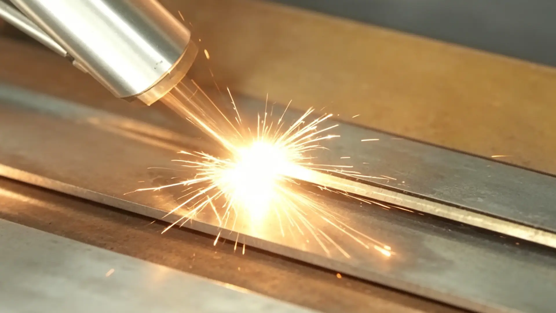
Spot size is the parameter most buyers never ask about. Halve the spot diameter and you quadruple the energy density.
Minimum spot size rule: Should be ≤ one-half to one-third of the defect size.
-
0.1mm pinholes → 0.04–0.06mm spot
-
0.2–0.3mm surface defects → 0.08–0.15mm spot
-
Cavity fills → 0.6–1.5mm spot
A system that covers the full range needs adjustable spot control from 0.05–1.5mm. Variable collimation assemblies give continuous spot tuning with no hardware changes.
The viewing system matters as much as the optics. Practical magnification is 10–25× total. CCD resolution at 1920×1080 with a 2mm field of view gives 1–2 µm per pixel – enough to resolve a 50µm spot boundary.
For deep cavities: Move to a longer focal length lens (f=200–300mm). Spot size grows to 80–120µm, but depth of field extends to 0.5–1.0mm and working distance opens up.
Step 5: Match Working Envelope to Your Jobs
Working envelope mismatches are silent killers.
Calculate travel from your actual mold population: X travel ≥ maximum mold length × 1.15. Y travel ≥ maximum mold width × 1.15. Z travel ≥ mold height + fixture height (100–200mm) + welding head unit (150–250mm).
Small jobs need attention too. Specify Z-axis lower clearance ≤ 50mm to the table surface. Keep riser plates on hand.
Open frame vs. enclosed cabinet: For molds above 2 tonnes, open-frame gantry lets a bridge crane drop the mold straight in. Enclosed cabinets add 15–30 minutes per large mold change.
3-axis vs. 5-axis: More than 30% of your annual repair volume involves deep cavities or angled surfaces? The 5-axis premium pays back within the first year. A 5-axis system finishes a complex automotive mold in 5–7 hours. A 3-axis machine takes 8–10 hours.
Step 6: Assess Control Software
Software is where expensive machines become cheap liabilities.
Material parameter presets: A solid library cuts new-operator setup time from 30–60 minutes down to 5–10 minutes. First-weld scrap rate drops from 8–12% to 2–4%.
What makes a preset library worth specifying: coverage of at least 20 mold steel grades, auto-scaling based on repair depth, scene templates, and import/export capability.
Advanced path functions: Manual programming of a circular cavity edge takes 10–20 minutes. Software-generated path: 1–3 minutes. That’s 70–90% of programming time back in production.
Overlap control locks within ±5% vs. uncontrolled drift of 20–40%. Porosity and fusion defects fall 30–50%.
Step 7: Verify Material Compatibility
The steel grade on your mold determines every welding decision.
How common mold steels behave:
-
P20 (28–32 HRC): Forgiving. Low cracking risk.
-
H13 (46–52 HRC): High alloy content means the HAZ cracks once heat input goes past its limit. Preheat to 250–350°C. Stress-relief temper is not optional.
-
S136 / 420SS: Need filler wire matched to high-chromium stainless group.
Post-weld machinability check: Spot-check weld hardness. Drag marks or surface darkening on grinding point to uneven microstructure. On S136 and 420SS, a filler mismatch shows up as boundary lines and fogging during polishing.
The Buying Checklist
Run through these boxes before you sign anything.
Laser source & pulse capability: High-energy pulse mode (≥10 J/pulse). Independent control of pulse energy, width, and frequency. Process packages for H13, P20, S136 minimum.
Power & energy window: Minimum pulse energy ≤ 1 J. Maximum ≥ 30 J. Frequency ceiling ≥ 30 Hz. Average power 50–200 W.
Optics & spot size: Adjustable from ≤ 0.2 mm to ≥ 1.5 mm. 10× microscope observation system.
Working envelope: X/Y/Z travel clears your largest mold plus 15% margin. Repositioning accuracy ≤ ±0.05 mm.
Control software: Built-in mold steel parameter library (≥10 presets). Automatic weld parameter logging.
Material compatibility: Tested on ≥8 mold steel grades. Filler wire pairing chart included.
Vendor support: Remote response ≤ 4 hours. Critical spare parts ≤ 5 business days. Minimum 2 days on-site training.
Conclusion
The right laser welder for mold repair isn’t the most powerful one. It’s the one that fits your specific steels, your tightest tolerances, and your production schedule.
You now have a clear framework: evaluate laser welding parameters for mold steel, assess optical precision, verify material compatibility, and challenge any supplier’s claims before signing anything.
Take the buying checklist from this guide and run it against actual machines. The gaps will show you where each system falls short.
Need a recommendation built around your repair volume and mold types? Maxwave delivers fiber laser welders engineered specifically for precision mold repair – with stable beam quality, adjustable spot optics, and material presets for P20, H13, and S136. Talk to a Maxwave specialist. Bring your specs. Get a straight answer.