
Sheet metal deformation doesn’t warn you — it shows up as a warped panel, a bent edge that won’t close flush, or a finished part that fails inspection after hours of work.
You might be chasing sheet metal springback compensation on a high-volume press line. Or troubleshooting thermal deformation in metal fabrication from a single weld pass. Either way, the frustration is the same: something that should be flat, isn’t.
The good news? Most deformation problems follow predictable patterns. That means they have real, systematic fixes. Below is a practical breakdown — what went wrong, why it happened, and how to correct it.
Identifying the Type of Deformation Before You Act
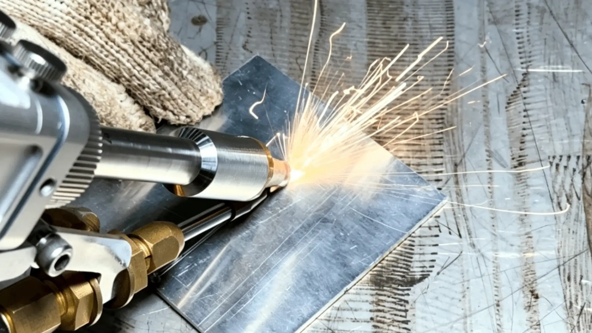
Treating every deformation the same way is one of the most expensive mistakes in sheet metal work. Correct a springback problem using warping logic, and you don’t just fail to fix it — you make it worse.
The root cause matters. The correction path depends on what you’re looking at. Here’s a fast, field-tested way to read what your part is telling you.
Six Deformation Types — and How to Spot Them
| Type | What You See |
|---|---|
| Warping | Full panel won’t sit flat; edges rise and fall with no single fold line |
| Twisting | Opposite corners sit at different heights — the part looks wrung out |
| Springback | Angle opens up after unloading; no cracking, just elastic recovery |
| Tearing | Visible cracks at holes, sharp corners, or high-strain edges |
| Local bulging | Small raised areas that bounce back when pressed |
| Feature distortion | Holes go oval, flanges drift, ribs collapse or elongate |
A 4-Step Field Diagnosis
Step 1 — Global or local?
Full-panel distortion? That points to warping, twisting, or springback. Isolated cracks or bumps? Those point to tearing, bulging, or feature-level failure.
Step 2 — Continuous curve or a hard break?
Smooth, flowing surfaces signal elastic or thermal deformation. Sharp lines and open edges signal localized yielding or tearing.
Step 3 — Is there a dominant direction?
One-axis curvature points to springback. Diagonal height differences point to twisting.
Step 4 — Does it cluster near features?
Deformation near holes, flanges, or ribs? Check die radius, stress concentration, and draw ratios first. Deformation across open flat areas? Check residual stress, clamping sequence, and heat input.
The Fast Root-Cause Split
Name the deformation type first. Then trace it to one of three origins:
- Design geometry — same failure at the same location, every batch → check corner radii, feature spacing, local stiffness
- Process operation — results vary by shift or machine → check bend sequence, clamping, weld order, cooling path
- Material and residual stress — wide batch variation, strong springback after unloading → check yield strength, plate thickness consistency, rolling direction
One rule holds across all three: name the type before you apply any correction. Pressing flat won’t close a tear — it widens it. Adding forming force won’t fix springback — it builds more residual stress and sets up the next failure.
Root Causes of Sheet Metal Deformation in Processing
Three categories drive almost every sheet metal deformation problem: design geometry, process execution, and material behavior. Get the category wrong, and your correction effort goes nowhere. Get it right, and the fix becomes obvious.
Design Geometry: Where Problems Get Baked In
Bad geometry doesn’t fail at random — it fails at the same location, every single batch. That’s the tell.
Cut features placed too close to bend lines are one of the most common silent culprits. Laser and plasma cutting leave high thermal gradients and residual stress along every edge. A slot or hole within 1–2× material thickness from the bend line has nowhere to release that stress. The result: oval holes, uneven bend angles, and edge waves. The fix is straightforward — keep cut features at least 3–4× material thickness (3–4t) from the bend line. On 2 mm cold-rolled plate, moving a slot from 2 mm to 8 mm away from the bend line can wipe out a 1–2 mm wave edge.
Flange length matters more than most people expect. A flange shorter than 3t doesn’t give the press brake enough clamping surface. The edge buckles under pressure instead of forming a clean bend. Industry standard puts the minimum straight flange at 4–6t. On 1.5 mm stainless, a 3 mm flange produces 0.5–1 mm of end-tip warping. Extend it to 9 mm and that drops to under 0.2 mm.
Missing relief slots at internal corners create another predictable failure point. Two bend lines crossing without a relief cut put material from both sides competing in the same zone. You get a bulge, crack, or twist at the corner. A slot width of 1.0–1.5t, with depth extending past the bend intersection, clears the stress path. On 1.2 mm plate, an unrelieved l-corner generates 0.4–0.6 mm of bulging. A correctly sized slot brings that below 0.1 mm.
Asymmetric cross-sections add torsion to every bend. The section’s center of gravity sitting more than 2–3t from the bend line forces the press brake to generate an unintended twisting moment alongside the intended bend. On a 500 mm aluminum part with just 5 mm of centroid offset, far-end twist can reach 3–4 mm — a tolerance failure on most drawings.
Process and Tooling: Where Variation Enters the Picture
Geometry failures repeat in the same spot. Process failures shift by shift or Machine to machine. Same drawing, different result — that’s the signal.
V-die opening selection carries more influence than it looks. The standard working range runs 6–10t, with 8t as the common cold-rolled steel default. Drop below 5t and forming force spikes. The sheet pulls unevenly and springback becomes unstable. Go above 12t and the material flows too loosely — flanges warp and angle consistency drops.
Punch misalignment introduces asymmetric loading that bends and twists at the same time. On 1.5 mm high-strength steel with a 12 mm V-die, a 1 mm punch offset produces a 3–4 mm bow across a 400 mm part. Even 0.5 mm of offset — about 4% of the V-opening — generates measurable bow under production conditions.
Unsupported long plates sag under their own weight during bending. For 1–2 mm steel plate at 1 m length, 10–20 mm of deflection without a support stand produces 1–2° of angle variation end-to-end. Parts can look bent correctly and still fail dimensional inspection.
Single-pass forming of complex geometry concentrates strain in an uneven pattern. Total bend angles above 150°, or large flanging operations, should be split into 2–3 progressive passes with intermediate flattening. In practice, this cuts overall deformation by 30–50%. For high-strength steel (yield ≥ 600 MPa), splitting passes isn’t optional. One-pass springback on these materials is too large and too unpredictable to fix after the fact.
Material and Residual Stress: The Hidden Starting Condition
Your sheet metal is already carrying stress before you make the first cut. Coil stock arrives with built-in curvature from the rolling process — longitudinal bow with natural radii of 1–3 m, edge waves reaching 2–5 mm on 1 m-wide plate. Thermal cutting adds another layer. Laser and plasma operations create temperature differences of several hundred degrees Celsius along cut edges. Those edges cool at different rates, contract at different rates — and the sheet moves.
Multi-roll leveling before processing can reduce pre-existing residual stress sheet metal problems by 30–70%. Flatness error drops from several millimeters to under 1 mm. Skip this step and you’re correcting deformation that existed before forming even started.
welding heat input takes this further. On thin plate (1–3 mm), a single 500 mm weld bead can produce 3–8 mm of edge warping as the weld zone contracts during cooling. Aluminum is particularly sensitive. Its thermal conductivity runs 3–4× higher than carbon steel, and its expansion coefficient exceeds steel by 30–40%. That makes the heat-affected zone wider and the distortion more severe. Stainless steel runs the opposite problem. Low conductivity means heat stays concentrated in a small area. Slow cooling builds high residual stress and persistent angular distortion.
Cold working raises yield strength — and springback with it. Each forming pass work-hardens the material. The same 90° bend that springs back 1–3° on low-carbon steel springs back 8–15° on high-strength steel at 600–1000 MPa yield. That’s not a machine calibration problem. That’s a material state problem. The forming sequence can create significant hardening before the final bend. You need to account for the elevated springback before programming the overbend — not after measuring the finished part.
How to Correct Springback in Sheet Metal Bending
Springback is physics, not error. Release a bent part from the press, and the elastic zone in the cross-section recovers. The angle opens, the curve flattens, and the part you programmed is no longer the part you’re holding. You can’t eliminate this. You can predict it, measure it, and compensate for it with enough precision that it stops mattering.
That’s the real mindset shift: stop chasing zero springback. Start building a system where springback is a known variable.
The Numbers You’re Working With
Springback varies by material. The range is wide enough that treating all materials the same will destroy your tolerances:
| Material | Typical Springback (single V-bend, inner R ≈ t) | Recommended Overbend |
|---|---|---|
| Cold-rolled steel | 0.75–1.0° | +1–2° |
| Hot-rolled steel | 0.5–1.0° | +1–2° |
| 5052 Aluminum | 2–5° | +3–5° |
| 304 Stainless | 2–5° | +3–5° |
| Copper / Brass | 0–0.5° | +0–1° |
One rule that cuts through a lot of trial and error: with inner r ≤ t, many production shops bank a flat 5° springback allowance as the air-bending starting point. From there, fine-tune ±1–2°. It’s not elegant, but it works as a first-pass default.
Radius matters too. Push the bend radius above 2t and your springback angle can run 50–100% higher than the table values above. Larger radius means more elastic recovery. Adjust before you cut the first part.
Three Forming Methods, Three Levels of Control
The process you choose determines how much springback you’re fighting — and how tightly you can control it.
Air bending gives you the most flexibility across part geometries. The trade-off is more springback. Cold-rolled steel comes in at 1–3°; stainless can hit 3–5° or higher. The fix is overbend compensation combined with real-time angle measurement feedback. Modern CNC press brakes with laser angle measurement can hold ±0.25–0.5° repeatability — accurate enough for most production work.
Bottoming presses the sheet into the V-die until it conforms to the tool geometry. The plastic zone grows. The residual elastic stress spreads out. Springback drops compared to air bending, and angle repeatability improves. You’ll need 2–3× the tonnage of air bending, plus a dedicated V-opening. For parts requiring ±0.5–1° angular tolerance, it’s the most practical middle ground.
Coining takes the cross-section to near-complete yield. Springback drops to 0–0.5°, and angular precision can reach ±0.2–0.3° — the tightest you can get in standard press brake work. The cost is real: tonnage runs 5–10× air bending, and die wear picks up fast. Reserve coining for high-fit-up parts where gap tolerances run under 0.1 mm.
The Iterative Overbend Method — For High-Precision Work
Standard compensation tables sometimes fall short. This closed-loop approach gets you to ±0.2–0.5° without guessing:
- Set a conservative initial bend depth — a bit less than target
- Form the part, measure the angle under load
- Release, measure again — record the springback angle (θ_f)
- Calculate the effective material parameters from the delta
- Values converge with the previous run? Calculate final bend depth and form to completion
- No convergence? Repeat until they do
Yes, it takes more first-article time. It also saves you from scrapping a full batch.
Process Adjustments That Cut Springback at the Source
Beyond overbending, several process changes reduce springback:
- Tighten the inner radius — dropping from R = 1.5t to R = 1.0t can cut springback angle by 30–50%
- Narrow the V-die opening — a tighter V increases forming strain and raises the plastic zone ratio
- Orient the bend line perpendicular to the rolling direction — this cuts springback variation and lowers cracking risk on high-strength materials
- Add local embossed ribs on high-strength steel — the extra plastic stretching bleeds off residual elastic stress before springback builds up
For critical aerospace or automotive parts, stretch forming or post-form stress-relief annealing can push springback close to zero. The cost only makes sense for tight-tolerance structural parts, though.
Using Simulation
CAD/CAE springback compensation simulation earns its place on complex parts. Feed in your material’s elastic modulus, yield strength, hardening curve, tool geometry, and friction coefficient. The solver runs the full load-unload cycle, calculates the springback field, and generates a compensated tool geometry — the “anti-shape” that accounts for elastic recovery.
In practice, simulation compresses die tryout from the traditional 5–10 trial runs down to 1–3. Springback error drops from over 3° to under 1°. On complex surface forming — think automotive body panels — surface deviation RMS falls from 1.0–1.5 mm to 0.3–0.5 mm after compensation.
It’s not a replacement for process discipline. It’s what you reach for when overbend tables and iterative trial runs can’t get you to spec.
Fixing Warping and Twisting: Design-Level Corrections
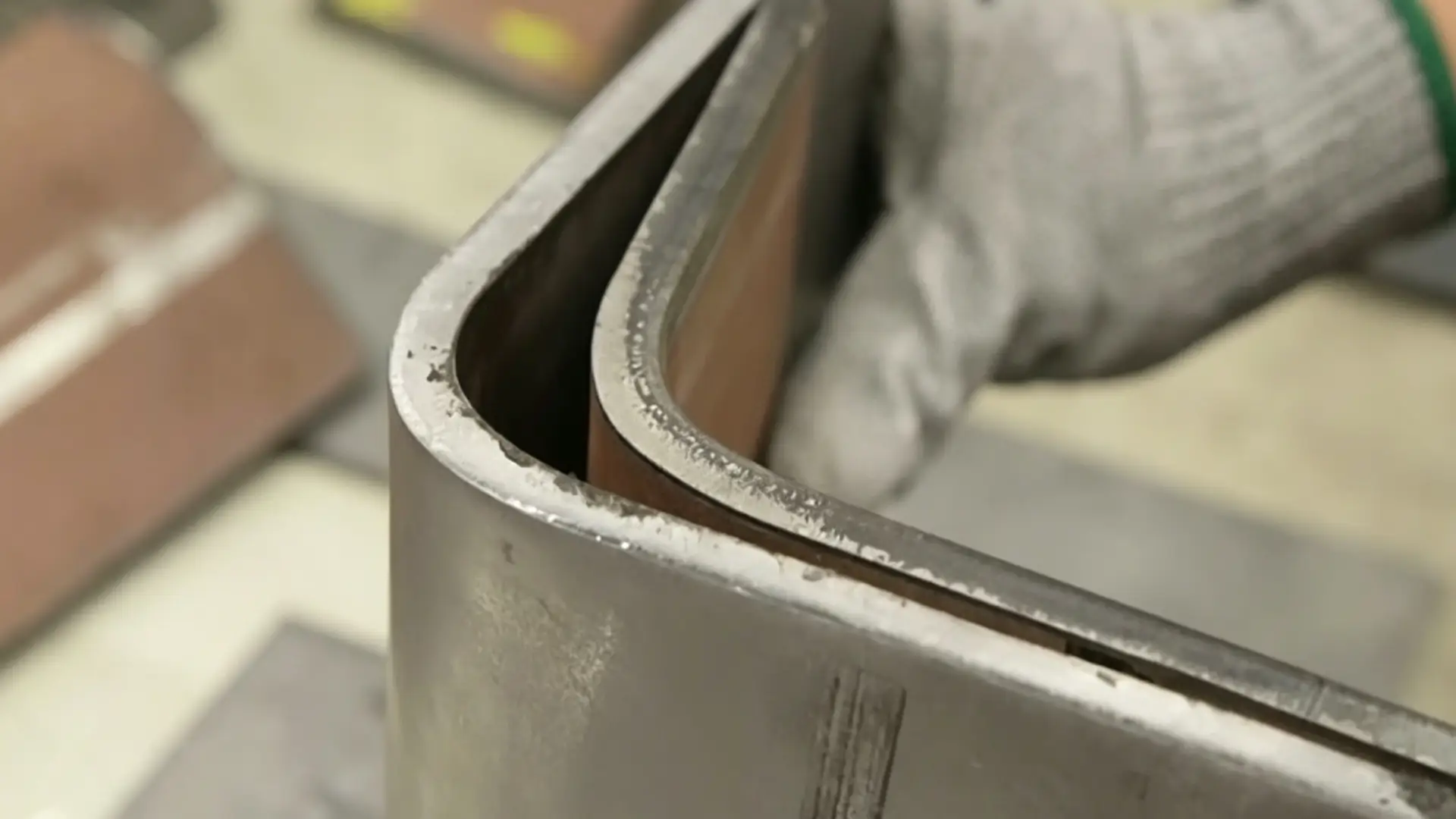
Warping and twisting are design failures dressed up as process problems. Check the drawing before you touch a single machine parameter. Most of these issues are built into the geometry long before the sheet reaches a die.
Keep Features Symmetric Across the Bend Line
The bend line is the axis where strain distributes. Put more material removal on one side than the other, and the sheet pulls toward the lighter side every time. Your target: area removed or formed on each side of the bend centerline should match within 10–15% of total removed area over the bend length.
Long flanges exceeding 10×t need extra attention. Add opposed flanges or stiffening beads on both sides. This balances the tensile and compressive strain running along the bend.
Set the Right Hole-to-Bend Distance — and Do the Math
Holes and slots placed too close to a bend line are one of the most common sources of warping and edge distortion. The minimum safe distance A from hole edge to inside bend tangent follows two rules. Use whichever gives the larger number:
- A ≥ 2.5×t + Ri
- A ≥ 0.5×V (half the die V-opening)
In practice: t = 2.0 mm, Ri = 2.0 mm, V = 16 mm → A ≥ max(7.0 mm, 8.0 mm) → use 8 mm. Using high-strength steel above 600 MPa or tight radii where Ri < t? Add another 1×t as margin.
For elongated slots running parallel to the bend, keep the slot end at least (2.5–3)×t + Ri from the bend line. Can’t achieve that clearance in the layout? Cut a relief notch between the slot end and the bend. This breaks the stress path before it spreads as a wave.
Control Flange Length and Coverage to Fight Twisting
Short, intermittent flanges invite twisting. A flange that covers one end of a 200 mm bend stiffens that end — the rest stays free to rotate. The rule: continuous flange coverage should reach at least 50–60% of total bend length. On that 200 mm example, that means ≥100–120 mm of engaged flange.
Flange height matters just as much. For standard mild steel sheet, keep h ≥ 3×t to build real torsional resistance. Drop below 2×t and the flange adds almost nothing — it’s shape without stiffness. On thin sheet at t ≤ 1.0 mm, raise that minimum to h ≥ 5×t.
Use Bend-Relief Slots at Tapered Flange Ends
A flange that starts or stops along a bend — on tapered or partial-length flanges in particular — concentrates stress at the transition point. That’s where twisting and local warping start. The fix is a correctly sized bend-relief slot at each termination point:
- Relief depth Dr ≈ 1.2–1.5×Ri (example: Ri = 2.0 mm → Dr = 2.4–3.0 mm; use 3 mm)
- Relief width Wr ≥ 1.5–2×t for high-strength materials (example: t = 1.5 mm → Wr = 2.25–3.0 mm)
- Internal slot corners: radius ≥ 0.5×t to prevent cracking
Standardize Your Bend Radius Across the Whole Part
Mixed bend radii on the same panel cause unequal neutral-axis shifts, unequal flange elongation, and residual stress that builds into global warping after forming. The simplest flatness fix at the design level: use one standard inside bend radius across all bends of the same angle.
For mild steel, that’s Ri = 1.0–1.5×t. For stainless or high-strength steel, use Ri = 1.5–2×t. Build this into your CAD bend table and enforce it at tooling selection. Don’t mix tight bends (Ri ≈ 0.5×t) with large radii (Ri ≥ 3×t) on the same panel. Use relief cuts or stiffening beads to separate them if you must.
Large flat panels wider than 30×t that take multiple bends need one more step. Add stiffening beads parallel to the major bend lines, with bead depth of (0.5–1.0)×t. This locks in post-forming flatness before the part leaves the press.
Process-Side Corrections for Sheet Metal Deformation
Good tooling setup catches problems that no post-forming correction can fix. Before reaching for a press or a straightening roller, check the machine first.
Tooling Setup: The First Line of Defense
V-die width determines how well the sheet is supported during bending. The working rule: V-opening should fall between 8–10× material thickness (t). Too wide, and the bend zone loses support — you get local indentations and collapse. Too narrow, and the material buckles sideways into visible bulges.
Inner bend radius follows a similar logic. Hold Ri ≥ 1.0–1.5t. Go tighter than that and you invite cracking, increased springback, and edge lifting. This is a real concern on softer materials like aluminum alloys. Those need a larger radius or a pressure pad to prevent wave wrinkling along the V-die flanks.
Punch alignment is quieter than it looks, but its effects aren’t. A center offset greater than 0.1–0.2 mm on small-to-medium parts produces left-right angle differences of 1–3° and introduces local twisting. Your diagnostic: measure the bend line position on the first article using an angle gauge or 3D scan. One side reads high, the other reads low — that’s a punch centering problem.
Back gauge position and support height control flange quality at the far end of the part. Keep flange length at ≥ 4t. Shorter than that, the back gauge clamping point sits too close to the bend line and buckles the edge. Flange height must meet H ≥ 2t + r. Drop below this, and the material can’t build full die support through the bend stroke. The result: roll-bending and side bow.
Large flat panels and thin sheet (t ≤ 1.0 mm) sag under their own weight without roller supports. That sag creates flatness errors exceeding 1–2 mm per 300 mm after forming. Add follower roller brackets or dynamic support before the bend — not after.
Secondary Forming Corrections
First-pass forming sometimes produces deformation that design or tooling changes can’t fix. Three correction processes cover most real-world situations.
Press correction handles moderate warping and twisting — flatness errors in the 0.5–3 mm per 300–500 mm range — on low-carbon steel and aluminum alloys with good plasticity. Use a flat die and apply distributed pressure in small increments. Overloading causes reverse over-bending, which trades one problem for another. For high-elasticity materials, plan 2–5° of overbend compensation to account for springback on release. Pair press correction with bottoming — coining the sheet fully into the die cavity. This raises local plastic deformation and cuts both springback and residual distortion.
Stretch leveling tackles long-part end flare, edge waves, and global warping on large thin panels. Both ends get gripped and pulled to near or just above yield. This produces uniform plastic elongation that releases localized internal stress. Roll-formed or press-brake-formed parts with end-flare distortion respond well to stretch forming or stress-relief annealing. Either option gives you a more uniform residual stress distribution than mechanical pressing alone.
Roll straightening handles continuous waves, twist, and bow in sheet strip or long-run parts — including coil-opened plate. The material runs through alternating small-diameter rollers. Those rollers impose repeated bending cycles in both directions, reducing residual stress through the thickness step by step. Set roller pressure differential at 1–5% of material thickness as your starting range. Exceed that and you introduce localized yield bands and surface marking. For severe global bow measured in multiple millimeters per meter, combine roll straightening with stretch leveling or annealing.
Stress Relief: When Mechanical Correction Isn’t Enough
Some deformation lives inside the material, not just on the surface. Mechanical correction moves the shape — it doesn’t always fix the stress state underneath it.
Annealing is the go-to fix for severe post-forming warping that mechanical straightening can’t hold. Low-carbon steel runs through full annealing at 650–750°C with a controlled cool. Aluminum alloys use stress-relief annealing at a shorter duration, around 300–400°C, with the exact temperature depending on the alloy series. In both cases, fixture thin parts flat during the heat cycle. The annealing temperature itself can introduce new distortion if the part sits unsupported.
Timing matters. Run annealing before critical-dimension operations like precision punching or CNC milling. Releasing residual stress after final machining shifts features out of position.
Aging treatment applies to high-strength aluminum (2xxx, 7xxx series) and precipitation-hardening stainless after stretch forming or spinning. Natural aging at room temperature over several days stabilizes light deformation on small, tight-tolerance parts. Artificial aging at 120–190°C for several hours speeds up the process and helps balance residual stress across the section. Severely warped parts need a two-step approach: mechanical straightening first to fix macro-geometry, then aging to stabilize the microstructural stress state.
Measurement Feedback: Closing the Loop
Corrections without measurement are just guesses repeated at scale.
Angle tolerance in production bending runs at ±1° as the general standard. Take first-article angle measurements with an angle gauge or 3D scanner and feed those results straight into the next run’s stroke correction. A useful conversion: 1° of angle error maps to roughly 0.05–0.1 mm of slider stroke adjustment, depending on the press model. Build this into a “measure → compensate → re-measure” cycle. Don’t treat first-article deviation as a one-time fix.
Flatness measurement uses a surface plate and feeler gauges for standard work, or laser scanning for tighter tolerances. Internal control targets sit at ≤ 0.5–1.0 mm per 300 mm. After roll straightening, take readings at 3–5 positions along the part length. Log the roller pressure settings alongside the flatness result. That data becomes your baseline for the next similar job — it cuts setup time and reduces rework on repeat orders.
General dimensional reference for cold-formed parts: linear dimensions hold ±0.1 mm, post-forming dimensions run ±0.4 mm, and bend-to-hole or bend-to-feature dimensions fall at ±0.2 mm. Keep hole spacing at ≥ 6t and hole-to-edge clearance at ≥ 2t. Sample at defined intervals — every 50–100 parts per shift is a common production rhythm — and keep the records. Patterns in the data show you where the process is drifting before it drifts into scrap.
Advanced Correction for Severe or High-Precision Deformation Cases
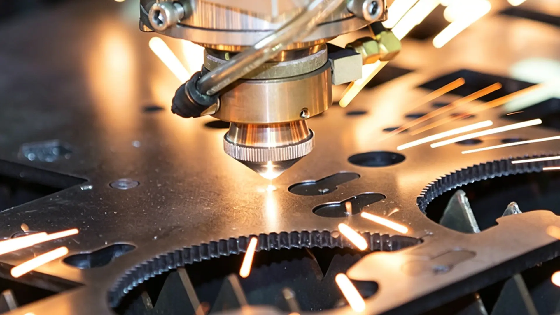
Some parts don’t respond to standard correction. Two press cycles, three rounds of roll straightening — and they still won’t hold tolerance. At that point, you’re not dealing with a process problem. You’re dealing with a system problem.
Stretch Forming for Severe Warpage
Large aluminum panels with warping beyond 5–15 mm — wing skins, fuselage panels, 1.5–6 mm thick, up to 12 m long — need stretch forming. There’s no way around it. The process pulls the entire sheet to 1–3% plastic strain. That puts stress just above the material’s yield point, well below necking risk. For 2xxx/7xxx aerospace alloys with yield around 350 MPa and tensile strength around 500 MPa, you’re targeting a stress window of 370–400 MPa.
The results are hard to argue with:
– Residual stress drops 40–70%
– Warp drops from 10 mm down to 1–2 mm
– Contour deviation stays within ±0.5–1.0 mm per 3 meters
Cold working alone can’t get close to those numbers. It builds localized plastic zones that push stress around in uneven patterns — and that creates a correction loop you can’t get out of.
Precision Process Control for Tight-Tolerance Parts
Aerospace and semiconductor sheet metal often runs hole-position tolerances of ±0.05–0.10 mm. Standard sampling doesn’t cut it at that level. Start with full 3D scans on the first 5–10 parts. That builds your process baseline. After that, scan 1 part for every 10–20 produced. Key features drift past 60–70% of the tolerance band? Adjust right away. Don’t sit on it and wait for a failure.
Track Cpk throughout. High-precision structural parts need Cpk ≥ 1.33. Safety-critical aerospace components push that up to Cpk ≥ 1.67. Your process can’t hold those numbers across 50+ parts per batch? The fixture or the Weld sequence needs a redesign — not another round of cold correction.
Prevention Checklist: Stop Sheet Metal Deformation Before It Starts
Most deformation problems are preventable. The best time to fix them is at the design stage — not after the part is already warped.
Go through this checklist before any part gets near a press brake or laser cutter.
Feature-to-bend clearance
– Holes: center-to-bend ≥ 2.5t + Ri
– Slots: slot edge-to-bend ≥ 4t
– All cut edges: ≥ ½ die V-opening from bend centerline
Flange length
– Minimum continuous flange: 4–6t; coverage must reach ≥ 50–60% of total bend length
– Got tapered flanges that drop below minimum length? Add a wedge-relief slot at the transition point
Bend relief slots
– Width ≥ 0.5t; depth ≥ R + t
– Internal corners: radius ≥ 0.5t — this stops cracking at the root
Bend radius minimums
– Mild steel: Ri ≥ 1t — Aluminum: Ri ≥ 1.5t — Stainless: Ri ≥ 2t
– Working with hard-temper 6061-T6? Set Ri ≥ 4t
Springback pre-compensation
– High-strength steel and stainless: pre-set bend angle at target + 2–3°
– Save your material/thickness/V-die springback values in the CNC program library. This cuts out per-job trial bending for good
Tolerance strategy
– Set tight tolerances (±0.1–0.2 mm) on critical locating features. That’s where precision counts
– Use ISO 2768-m for everything else. Over-tolerancing pushes you into rework — and rework adds new residual stress
Conclusion
Sheet metal deformation isn’t a failure. It’s a warning sign that something needs attention. The fix always starts in the same place: figure out why the metal moved. Then decide how to bring it back. That applies whether you’re dealing with springback on a precision bend, Welding warpage on a structural panel, or gaps in your prevention process.
The techniques covered here aren’t theoretical. Overbending compensation, stress-relief annealing, roller leveling, fixture-based correction — these are real, shop-floor tools. They’re what separates a team that scraps parts from one that ships on time.
Your next move: Audit your rejection rate for deformation-related defects. Higher than it should be? The root cause is almost always upstream — tooling setup, material selection, or process sequencing. Start there.