
You ran the laser over the weld. The discoloration disappeared. You moved on — and then, hours or days later, the oxidation was back. It looked like you never touched it.
Sound familiar? This isn’t a faulty machine or a flawed process. It’s physics.
Laser oxide layer removal does what it promises. The real issue is what happens to that bare metal surface the second cleaning stops. The metal is exposed. The air gets to work on it right away.
So why does oxidation return after laser cleaning welds? Three things drive it:
-
Passive layer chemistry — the metal surface rebuilds its oxide layer on contact with oxygen
-
Atmospheric exposure — the speed of that reaction depends on humidity, temperature, and air flow
-
Process variables — small adjustments most operators skip over entirely
Get those three things right. The results will hold.
What Actually Happens to Metal Surface When Laser Cleaning Removes Weld Oxide
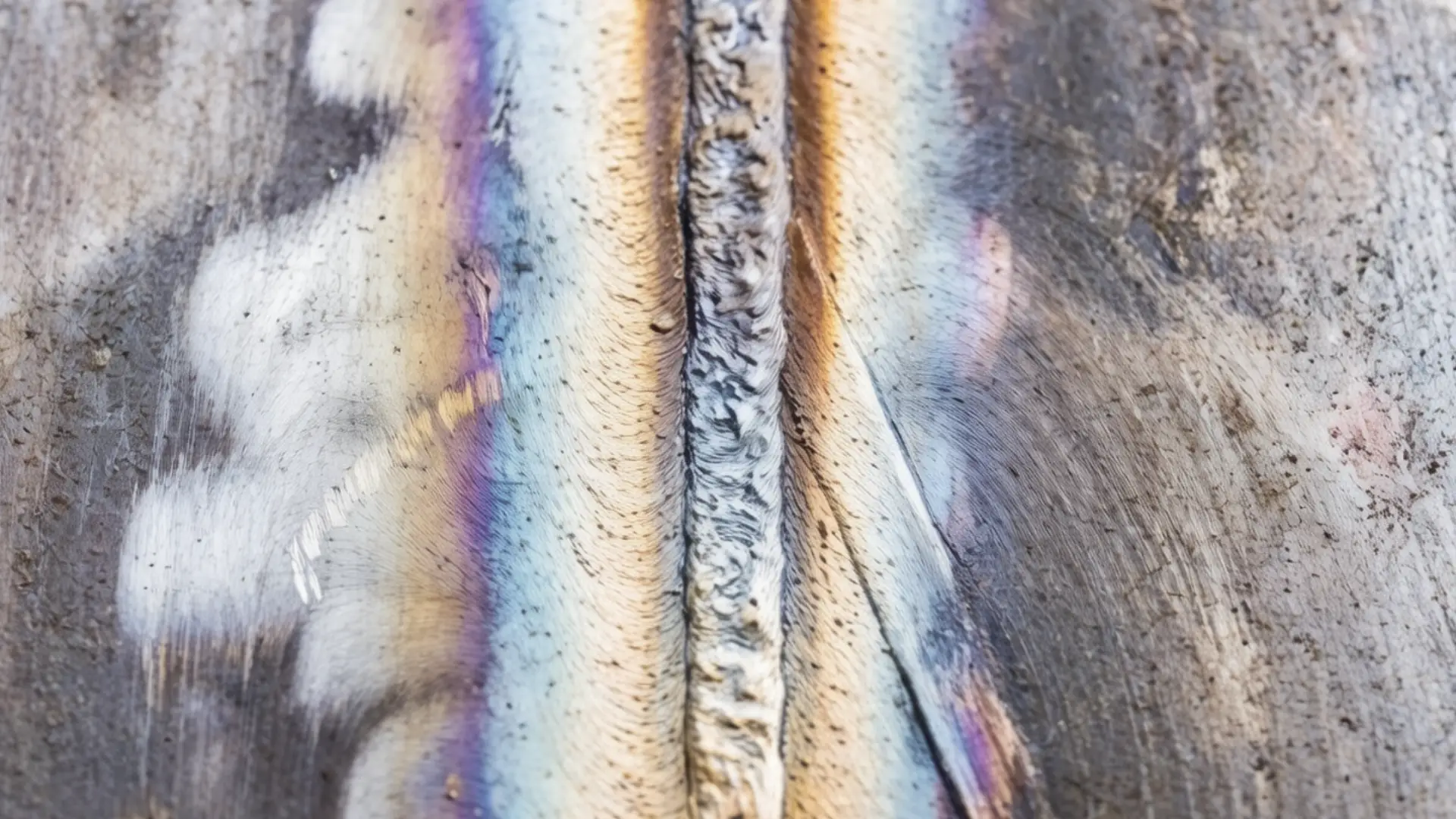
Most operators miss this: the laser isn’t scrubbing oxide off the metal. It’s destroying it at the molecular level. That distinction matters — a lot — for understanding why the problem keeps coming back.
Weld oxides — chromium oxides, iron oxides, the colored heat tints you see on stainless — absorb far more energy at 1064–1070 nm fiber-laser wavelengths than the clean metal beneath them. That gap in absorptivity is the whole mechanic. The laser fluence is set above the ablation threshold of the oxide, but below the ablation threshold of the base metal. The oxide vaporizes. The metal reflects the energy away.
Three removal mechanisms drive this. They all work at the same time:
-
Ablation and gasification — enough energy density converts the oxide layer into vapor and ejection products. It lifts off the surface and leaves nothing behind.
-
Thermal spallation — rapid heating expands the oxide faster than the metal beneath it. The stress breaks the adhesion bond. The layer peels away.
-
Micro-explosions — moisture or air trapped in surface micro-gaps absorbs energy, expands fast, and ruptures oxide islands that the first two mechanisms missed.
What’s left behind is bare, chemically active metal. That’s not a byproduct. That’s the goal.
But “bare and active” means something specific. On carbon steel, the exposed iron surface starts re-oxidizing within minutes in humid air. On stainless, the chromium-depleted heat affected zone oxidation layer is gone — but the new passive film hasn’t formed yet. On aluminum, a new native Al₂O₃ layer starts regrowing within minutes to hours. It’s thinner and more uniform than the weld scale it replaced, but it forms fast.
The laser cleaned the surface. It did not rebuild it. That gap between removal and restoration is where reoxidation on metal surfaces starts.
The Real Reason Oxidation Comes Back: It’s Not Your Machine, It’s Physics
Here’s the uncomfortable truth: the laser did its job. The problem is that the chemistry never stopped.
Oxidation is an electron-transfer reaction. Bare metal exposed to oxygen and moisture opens a reaction pathway — and it stays open. Laser cleaning removes the visible oxide layer. It does not close that pathway. The surface is clean, yes. But it’s also unprotected and sitting in open air.
That’s the gap. That’s where the problem lives.
Four environmental drivers push the reaction forward every time:
-
Oxygen exposure — the primary oxidizer, always present, always working
-
Moisture and humidity — water doesn’t just speed up oxidation. It acts as an ion transport medium, moving electrons across the surface faster
-
Temperature — a surface that looks stable at room temperature can re-oxidize hard and fast in hot service conditions or under direct sun
-
Salts and chlorides — these raise water’s electrical conductivity, which speeds up electron transfer across the surface
Clean off the oxide layer without controlling these four variables, and the surface rebuilds it. Not because the cleaning failed. Because the reaction pathway is still chemically available — the conditions that drive oxidation are still there.
Physical removal is temporary. Full stop. What you do after the laser pass — shielding gas, passivation treatment, humidity control, barrier coatings — that decides whether the result holds for hours or for years.
5 Specific Triggers That Accelerate Oxidation Return After Laser Weld Cleaning
Knowing why oxidation returns is one thing. Knowing what’s pulling the trigger is what fixes the problem on the shop floor.
Five specific failure points cause the vast majority of reoxidation complaints after laser weld cleaning. Each one is controllable. None of them require a new machine.
Trigger 1: Shielding Gas That Stops Too Soon
The laser pass ends. The shielding gas stops. The metal is still above 300–400 °C — and oxygen partial pressure at the bead surface climbs above 50–70 ppm within seconds.
That’s all it takes. Weld heat tint returns within minutes.
The fix isn’t more gas. It’s longer gas. Trailing shielding must cover the bead for 2–5 seconds after the laser moves on. This gives the surface time to cool below the oxidation-critical threshold before it hits open air.
Practical specifications that hold up in the field:
– Gas type: Argon or N₂, purity ≥99.99%
– Flow rate: 15–30 L/min measured at the nozzle — not at the regulator
– Nozzle stand-off: 5–15 mm, laminar flow, no crosswind above 0.5 m/s
– Trailing coverage: minimum 2–5 s post-flow on stainless; thin sections need 1–2 s minimum, thicker sections need 3–4 s or more
One overlooked field cause: solenoid and hose leaks. Welds oxidize despite “correct” flow settings because the gas never arrives clean. Do a leak check before assuming your parameters are wrong.
Trigger 2: Surface Contamination Left Behind — or Reintroduced
Laser oxide layer removal cleans what it can see. It doesn’t reach oil trapped in micro-pores, moisture in surface gaps, or the organic salts left by an ungloved hand.
Those residuals don’t stay put. Under heat and humidity, a fingerprint on stainless develops visible brownish oxide within hours to a day. Residual oil vaporizes during welding, punches holes in shielding gas coverage, and creates oxidation bands right where the cleaning looked clean.
Research on 5083 aluminum backs this up. Laser cleaning reduced surface oxygen content by up to 75% compared to uncleaned material — but this result held up only with contamination controlled beforehand. Push power and scanning frequency too high on a contaminated surface, and oxygen content increases again. The laser roughens and activates the metal instead of cleaning it.
Steps to take right after laser cleaning welds:
– Solvent wipe with alcohol or acetone and dry fully before the next step
– No bare-hand contact on cleaned areas — gloves at all times
– 30–60 minute maximum between surface prep and welding on aluminum and stainless; past that window, re-clean before proceeding
Trigger 3: Too Much Heat Going In
High heat input doesn’t just create more discoloration during welding. It creates conditions where reoxidation of metal surfaces after laser cleaning becomes nearly impossible to stop.
Here’s the mechanism. Elevated interpass temperatures keep the heat affected zone inside the sensitization range — 450–850 °C for stainless — longer than needed. Chromium depletes from the grain boundaries. Heavier, more stubborn oxide films form. Laser ablation removes the visible layer. But the underlying microstructure stays chromium-depleted and rough. It re-oxidizes faster in service, often showing visible color change within days in humidity or salt-spray conditions. By contrast, low-heat welds managed well can take weeks to show the same change.
The control points:
– Interpass temperature limit: keep below 150–200 °C for most stainless grades
– Travel speed: faster travel, not just lower power — this limits total heat input without losing penetration
– Heat input target: stay under 1.0–1.5 kJ/mm on stainless (industry benchmark)
– High heat input already? Apply a nitric or citric acid passivation treatment right after laser cleaning. This rebuilds a stable Cr₂O₃ passive layer before service exposure.
Trigger 4: Laser Cleaning Parameters That Activate the Surface
This one surprises most operators. The laser cleaning parameters themselves can cause the oxidation problem they’re meant to solve.
Studies on nanosecond laser cleaning of aluminum show a clear pattern: oxygen content at the surface decreases first, then increases again as laser power and scanning frequency climb past an optimum point. The laser stops ablating oxide and starts creating craters, stripe features, and rough micro-topography. That increases actual surface area — and speeds up oxygen uptake.
At a cleaning speed of 0.5 m/min, surface microhardness increased by 8.6%. That tells you the near-surface microstructure is being changed, not just cleaned. Excessive overlapping passes or very low scanning speeds also create local heating cycles. Those cycles push the surface back into a re-oxidation window in open air, right after the oxide was removed.
Post weld surface treatment by laser works only inside a specific parameter window. There’s no single “magic” setting that works across all material thicknesses and contamination levels.
Practical parameter discipline:
– Avoid slow speeds at high power — speeds below 0.5 m/min combined with high power and frequency are the most common cause of re-activated, rough surfaces
– Reduce crater depth and stripe formation by moderating power and raising scan speed
– Verify with sample coupons: oxygen content starting to climb as you add more energy? Back off — you’ve crossed from cleaning into activating
Trigger 5: Shielding Gas That Isn’t What the Label Says
The cylinder says 99.99% argon. The weld still oxidizes. The laser cleaning result still doesn’t hold.
This happens more than operators expect. Chromium oxide weld surface problems traced back to gas issues fall into three categories:
-
Solenoid or hose leaks — gas purity at the torch drops far below cylinder spec, regardless of what the regulator reads
-
Contaminated cylinders — moisture above 20 ppm or oxygen above 50–100 ppm in the gas supply is enough to drive rapid heat tint return
-
Wrong gas entirely — oxygen-containing mixes meant for cutting, used on weld quality applications by mistake
There’s also a timing problem that often goes unnoticed. After any gas-off period, residual air sits in the delivery lines. At 15 L/min flow, you need to purge for 10–20 seconds before real shielding gas reaches the torch. Skip that pre-purge and the first weld section oxidizes while later sections don’t — a pattern that gets misread as a machine or parameter problem.
Pre-start checklist for gas system integrity:
– Confirm cylinder spec: Ar or N₂, ≥99.99% purity
– Measure flow at the nozzle: 15–30 L/min
– Soap-bubble test all line joints before each shift
– Pre-purge ≥10–20 seconds after any gas-off period
– Never use cutting-grade oxygen-containing gases on weld quality or color-critical work
These five triggers rarely work alone. Take a weld made with high heat input, cleaned with aggressive laser parameters, shielded by a gas line that wasn’t purged, then handled bare-handed and left in humid air — that surface re-oxidizes fast and hard. Address all five. Not just the obvious one.
How Laser Cleaning Parameters Control Whether Oxidation Returns
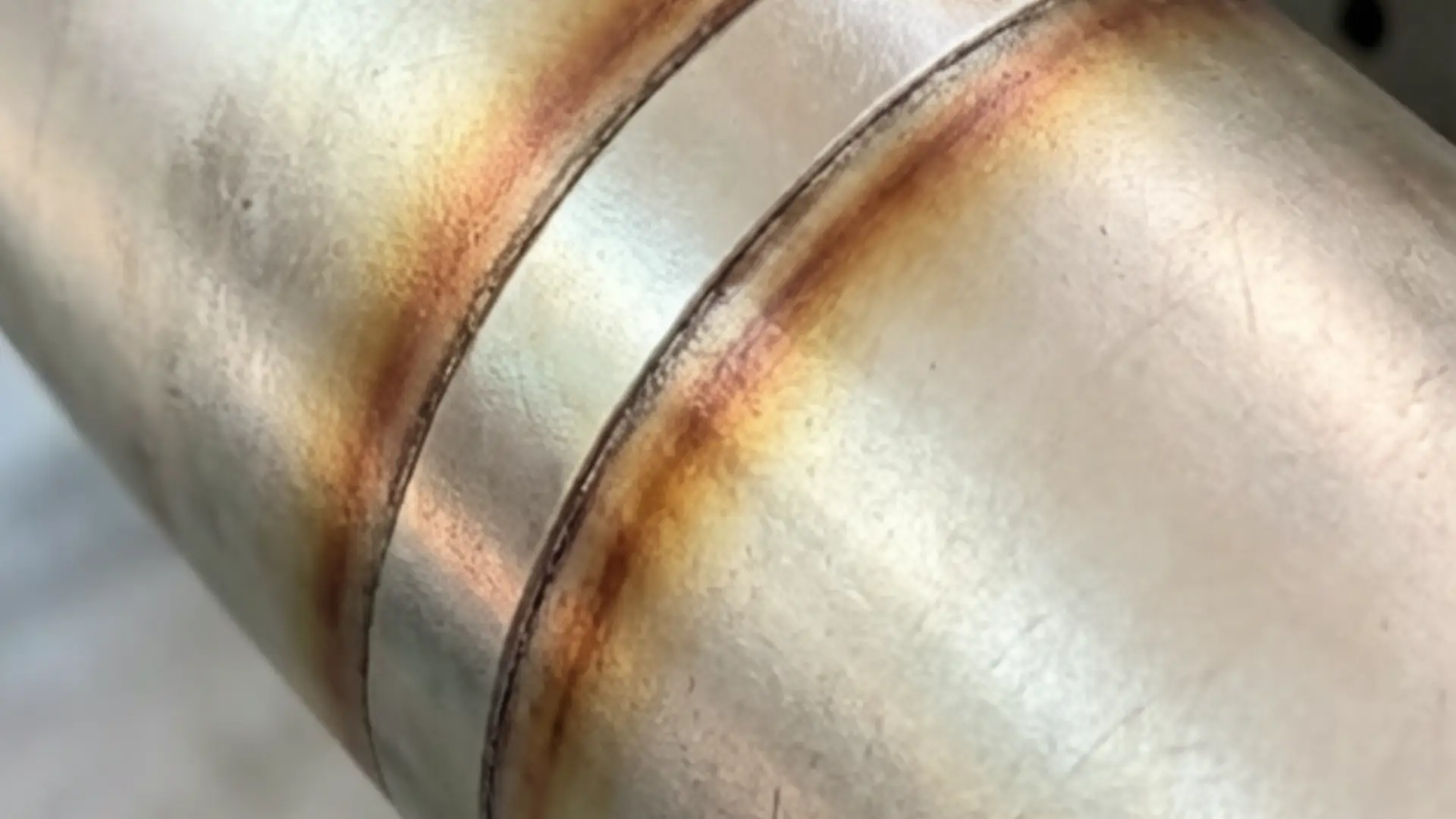
Every parameter you dial in — power, speed, pulse duration, scan width — does two jobs at once. The first job is obvious: remove the oxide. The second job most operators never think about: control how much heat gets left behind in the metal, and for how long.
That second job determines whether the oxidation comes back.
The core relationship is blunt. More energy per unit area means higher peak surface temperature and more time spent in the critical re-oxidation window (≈200–600 °C for steels). Push parameters past the optimum and you’re not just cleaning the surface — you’re preheating it for the next oxide layer.
The Four Parameters That Matter Most
Power and fluence set the ceiling. Higher fluence raises peak surface temperature and thickens the heat-affected zone. Push into substrate ablation and the surface roughens. More surface area means faster oxygen uptake and quicker oxidation return. For an 800 W unit on steel, 75% power at 20–40 mm/s is a solid starting point. For a 1200 W unit cleaning a 0.25 mm oxide layer, 95% power can work — but travel speed must hold at ≈20 mm/s to stop heat from building up.
Pulse duration changes the physics at a fundamental level. Nanosecond and picosecond pulses deliver massive peak power in very short bursts. Bulk temperature rise stays low. The oxide absorbs the energy and clears before heat moves into the substrate. CW and long-pulse modes work on a different principle — they deposit heat in a steady stream, thicken the heat-affected zone, and raise the chance of temper colors forming mid-clean. For thin oxide on aluminum or precision stainless work, pulsed regimes carry lower risk for keeping re-oxidation slow.
Scanning speed controls how long the laser dwells on each spot. Slower speed deposits more energy per millimeter, raises surface temperature, and extends exposure in the oxidation-active range. Too fast creates a different problem: incomplete oxide removal. Residual oxide patches act as starting points — the oxidation front rebuilds outward from them. The target is not the fastest or slowest speed. It’s the speed that achieves full removal without leaving excess heat behind.
Number of passes is the most underused control lever. Multiple moderate-energy passes beat a single aggressive one in almost every case. Each pass removes a layer without spiking the bulk temperature. The surface cools between passes. The heat-affected zone stays thin. Run one high-power pass instead and the result looks similar on the surface — but the substrate temperature climbs higher, roughness increases, and re-oxidation starts sooner.
The Practical Adjustment Sequence
Oxide removal comes up short, and most operators reach for more power first. That’s the wrong move. Use this sequence instead:
-
Add 1–3 passes at current power — limits temperature rise per pass, improves removal without stacking heat
-
Reduce scan width by 10–30% on stubborn spots — puts energy where it’s needed
-
Increase power in 5–10% increments — last resort only, watch closely for any discoloration
Heat effects show up as temper colors, slight discoloration, or a surface gloss change. At that point, run the adjustments in reverse: drop power 10–20%, raise travel speed 20–50%, widen scan width, then retest.
One verification step that closes the loop: after cleaning and cooling, check surface roughness against your baseline. A ΔRa within ±10–20% of the pre-clean baseline means the surface wasn’t over-processed. Roughness outside that range predicts faster oxidation return — the extra surface area speeds up oxygen uptake no matter how clean the metal looks right after the laser pass.
The parameter window that works isn’t wide. But it is findable. Lock it in with test coupons on your specific material and oxide thickness, and laser cleaning effectiveness on welds holds up in a way that single-pass aggressive cleaning never does.
Shielding Gas Strategy: The Most Overlooked Variable in Laser Weld Cleaning Oxidation
The cylinder reads 99.99% argon. The flow rate looks right on the regulator. The weld still oxidizes — and nobody in the shop can explain why.
Shielding gas isn’t a background detail. It’s an active part of whether laser oxide layer removal holds or fails. Get one variable wrong — purity, flow rate, nozzle geometry, post-flow timing — and the cleaned surface re-oxidizes before it cools. The laser did its job. The gas strategy didn’t.
Flow Rate: More Is Not Better
The instinct is to push flow higher when oxidation appears. That instinct is wrong about half the time.
For stainless steel laser weld cleaning, target 15–18 L/min argon at the nozzle. That’s the nozzle reading — not the regulator. Go too low (under 10 L/min on open joints) and visible heat tint develops 2–5 mm from the weld toe on polished stainless. Go too high (above 25 L/min through a small nozzle) and the flow turns turbulent. Turbulent flow pulls ambient air into the shielding zone. You end up with scattered oxidation spots that look random — but they’re not.
Helium on aluminum and reflective metals runs at a different range: 20–40 L/min. Turbulence risk climbs at the upper end. To keep gas velocity low, increase the nozzle inner diameter.
The optimization method is simple:
– Start at mid-range
– Step down until tint appears
– Step back up 2–3 L/min
Use the lowest effective flow that maintains laminar coverage — not the highest flow you can push through the line.
Purity Thresholds That Matter
Gas purity has a hard floor. It’s lower than most operators expect.
For stainless welds needing cosmetic quality — food grade, pharma, visible surfaces — use 99.995% argon with moisture below 10 ppm H₂O. That’s the working spec. Standard 99.99% argon covers most industrial jobs. Drop to 99.9% purity (0.1% oxygen contamination) and visible discoloration returns on high-spec stainless — even with everything else dialed in.
For aluminum, watch the oxygen concentration at the surface. Above 50 ppm O₂, oxide film thickness grows at the weld and HAZ. That makes post weld surface treatment harder and cuts cleaning effectiveness. TRUMPF’s controlled-atmosphere chamber approach uses tight gas flow control, continuous O₂ monitoring, and high-purity argon or helium. That system exists because standard bench shielding can’t hold aluminum below that 50 ppm threshold with any reliability.
Nozzle Geometry Controls the Physics
TC4 titanium data shows why geometry matters so much. Titanium needs shielding above 480 °C to avoid oxidation coloring and mechanical property loss. That temperature window is unforgiving.
Three nozzle variables decide whether the shielding gas covers the hot zone:
-
Nozzle height: Lower stand-off (within the 5–15 mm range) tightens coverage over the high-temperature zone. It also cuts oxidation bands at the edges.
-
Nozzle inner diameter: A larger ID at higher flow rates keeps gas velocity low. This holds laminar behavior and suppresses the plasma plume that traps oxidizing gases near the surface.
-
Nozzle angle: Coaxial alignment beats angled delivery for covering the HAZ and clearing plume-driven oxide deposits.
These same relationships apply to stainless chromium oxide weld surface cleaning. Coaxial delivery — gas routed through the center of the laser head — gives the most stable coverage and keeps local oxygen pockets to a minimum.
Pre-Flow, Post-Flow, and the Gap Nobody Closes
Two timing gaps produce oxidation problems that operators misread as parameter or machine failures.
Pre-flow: Run at least 0.2 seconds of gas flow before the laser starts. Skip this step and residual air in the delivery line oxidizes the first section of every cleaning pass. You’ll see it as inconsistent results across a single weld bead.
Post-flow: The surface stays above the critical oxidation threshold for several seconds after the laser stops. Use this post-flow calculation borrowed from arc welding: welding amps ÷ 10, minimum 8 seconds. Hold the nozzle over the bead until the post-flow cycle finishes and the metal drops below the oxidation-active temperature range.
Skip either window and passive layer regeneration starts in open air instead of under inert cover. It never catches up.
System Integrity: Where “Correct” Settings Fail
Correct flow rates and purity specs can’t fix one specific source of reoxidation on metal surfaces: leaks inside the delivery system.
Loose collet bodies, damaged insulators, and oxygen-service hoses used in place of dedicated inert-gas lines all push contamination into the gas stream between the cylinder and the nozzle. The regulator reads fine. The gas at the surface does not.
Run a pre-shift integrity check every time:
– Soap-bubble test all line joints before starting
– Confirm the nozzle connection — tighten the collet body before the back cap, not after
– Use dedicated inert-gas hoses only; pull any hose that saw oxygen service and don’t put it back
– On long gas lines, extend pre-flow time to clear residual air and avoid the high-velocity surge that triggers turbulence at the start of each cleaning pass
Fix the system first. Adjust the parameters second. Always in that order.
Stainless Steel Weld Discoloration After Laser Cleaning: Why Color Keeps Changing
The color isn’t stuck. That’s the problem.
Clean a stainless weld and it goes silver. Come back an hour later and it’s straw. Run another pass and it shifts to blue. The surface keeps moving — and it won’t stop until you know what’s controlling the color.
The answer is oxide film thickness. On 304 and 316 stainless, the colors you see — yellow, brown, purple, blue, black — each match a chromium and iron oxide layer between 20 and 300+ nm thick. That’s it. Color is just thickness. Change the thickness and you change the color.
Laser cleaning changes that thickness on every single pass. That’s why the color keeps shifting on every single pass.
Four mechanisms drive the cycling:
Local temperature keeps crossing the temper-color ranges. Each laser pass heats the surface at a different rate, depending on speed, overlap, and fluence. At 200–250 °C, the surface turns straw. At 280–320 °C, it goes blue. A slower pass in the same zone adds 100–200 °C to the peak temperature. Silver becomes straw becomes blue — on a surface you already cleaned.
Multilayer oxides peel off in stages, not all at once. Weld heat tint isn’t a single film. It’s a stack — thick iron-rich oxides on top, a thinner chromium-rich layer underneath. One pass strips the outer layer. The straw or brown you see afterward isn’t new oxidation. It’s what was already there, one level down.
Non-uniform beam energy creates patchy, shifting results. A Gaussian beam hits hardest at the center and tapers at the edges. With 50–70% track overlap, some zones absorb two to three times the energy of neighboring ones. Those hot zones turn blue or purple first. A later pass ablates them to silver. Meanwhile, cooler zones are still showing brown. The result looks random. It isn’t — it’s geometry.
Re-oxidation between passes starts a new color cycle. Strip the oxide and the bare chromium surface rebuilds a passive film within seconds in open air. That film is thin and hard to see. The next laser pass hits it before it stabilizes — and it will, if passes are spaced close together. That interaction produces a different color than the previous pass did. Same spot, different outcome, no clear reason.
Controlled studies on nanosecond pulsed fiber laser cleaning of austenitic stainless (1064 nm, 0.5–2.5 J/cm² fluence range) recorded this cycling in detail. At fluences above 1.5–2.0 J/cm² combined with scanning speeds below 100 mm/s, surface temperatures topped 300–400 °C. New temper oxides formed — straw, then blue — even after the original heat tint was gone. The sequence wasn’t random. It followed a clear pattern: brown → silver → straw → blue, tied pass-by-pass to temperature peaks and film thickness changes.
The parameter window that stopped the cycling was narrow: fluence held at ~0.8–1.2 J/cm², scanning speed between 100–400 mm/s, hatch spacing at 30–60 µm. Inside that window, the surface reached silver and held it. Outside it — the cycling sped up, chromium depletion went deeper, the surface got rougher (Ra up to 0.6–0.8 µm on over-processed zones), and the color kept coming back.
To stop the color from shifting, four controls work together:
-
Cap the peak surface temperature below 200–220 °C — push scan speed into the 200–500 mm/s range and drop fluence to just above the oxide removal threshold
-
Separate the heavy removal pass from the finishing pass — run higher fluence first to strip black and blue tint, then one fast low-fluence pass to even the result; stop at two to three passes total
-
Run shielding gas through the cooling phase — high-purity argon or N₂ at ≥99.99%, held over the bead for 2–5 seconds after the laser moves on; this blocks re-oxidation while the surface is still hot enough to react
-
Start from a lighter tint — light straw from a well-shielded weld cleans to stable silver far more consistently than dark blue or black; the thicker and more altered the original oxide, the more it will cycle
Color banding showing up as stripes or rings along the bead means uneven overlap. Adjust hatch spacing until each zone gets hit a consistent one to two times — not three, not four.
The surface goes silver but reverts to straw or blue hours later under service heat? The chromium-depleted sub-surface layer is still there. Laser cleaning removed the visible film. It did not restore the passive film chemistry underneath. Pair laser cleaning with chemical pickling or passivation in that case. That’s the one approach that fixes both the surface appearance and the underlying metallurgical condition driving it.
How to Prevent Oxidation From Returning: A Practical Protocol by Material Type
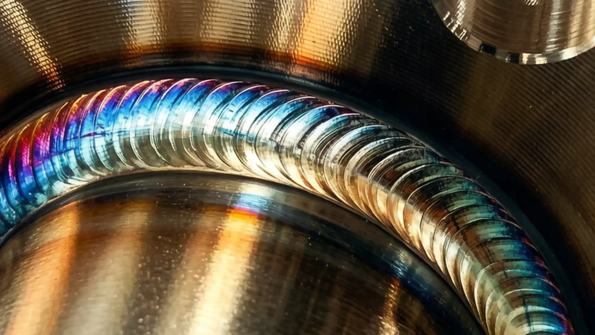
Each metal re-oxidizes in its own way. No single prevention protocol covers all of them. The steps below are sorted by material type. Start with the universal controls, then move to the specific protocols for each metal.
Universal controls — start here, no matter what material you’re working with:
Three things drive oxidation on every metal: oxygen, moisture, and temperature. Cut all three and the reaction slows down. Let any one of them rise and the cleaned surface builds its oxide layer back fast.
Practical starting point for any material:
– Clean before storage — don’t seal contamination under a protective layer
– Control humidity using desiccants (silica gel), dehumidifiers, or nitrogen purging
– Lower storage temperature where possible — oxidation rates rise with heat
– Limit air contact through vacuum sealing or inert-atmosphere packaging
– Separate dissimilar metals — galvanic contact speeds up surface damage on both parts
– Inspect and renew coatings before barrier layers wear thin, not after
By material type:
Carbon steel and iron — put on a zinc-rich primer or epoxy barrier coat right after laser cleaning. Galvanization gives the longest service life. For shop storage, follow this exact order: clean → dry → coat → desiccant storage. No skipped steps.
Aluminum and copper alloys — bare cleaned surfaces start re-oxidizing within minutes. Get barrier protection on or move to the next process step within a 30–60 minute window. For molten or casting work, flux with lime or borax and vacuum degas before the metal solidifies.
Graphite components — phosphate-based chemical inhibitors are the standard approach. Oxidation opens up tiny voids that turn into leak paths. Inhibitor loading stops this from happening — it’s not just a surface treatment.
High-temperature refractory metals — coating choice depends on service temperature, which ranges from 1,100°F to 4,500°F depending on the application:
– Molybdenum: silicon, nickel, chromium, or precious-metal coatings (gold, silver, platinum)
– Tantalum: beryllide, aluminide, or oxide-based systems — aqueous electroplating won’t work here
– Tungsten: a multi-coat stack is required; start with a rhodium base coat, then add nickel, chromium, or rhenium overcoats
Finished surface protocol — four steps that hold:
-
Strip oxidation fully before sealing — leftover oxide keeps reacting under any finish you put on top of it
-
Put the barrier on fast after cleaning: paint, sealant, wax, corrosion inhibitor, or clearcoat system
-
For painted or automotive surfaces, use synthetic polymer wax or sealant and reapply every 2–3 months
-
For metal storage, keep humidity low and air contact minimal — use desiccants, inert gas, or vacuum sealing
The barrier is what holds the result. The laser cleaned the surface. The protocol keeps it that way.
Troubleshooting Checklist: Oxidation Keeps Coming Back After Laser Cleaning
Nine failure points cause recurring oxidation after laser weld cleaning. Work through them in order. Most operators find their answer by the third checkpoint.
Block 1 — Did the Laser Remove the Oxide Fully?
Incomplete removal is the most common root cause — and the easiest to miss with the naked eye.
-
Benchmark starting point: pulse energy ≈ 1.5 mJ for metal oxide removal on a single-mode fiber laser
-
Oxide still there? Adhesion tests failing? Increase energy density in 5–10% increments or reduce scanning speed
-
Optimal parameter reference: 500 kHz pulse frequency / 50 µm line width / 15 mm/s scanning speed — start here, then adjust for your oxide thickness
-
Dark residual film still showing after one pass? Run 2–3 passes at 50–70% line overlap. Leftover oxide creates active corrosion sites. Those spots re-oxidize first and fastest
-
Pattern test: oxidation keeps showing up in the same patches? Those zones were undercleaned. Reduce hatch spacing or slow down in those areas
Block 2 — Are You Overheating the Base Metal?
Laser cleaning is self-limiting by design. Once the oxide clears, reflectivity rises and ablation efficiency drops on its own. Surface keeps darkening or roughening through extra passes? That’s not cleaning — that’s damage.
-
Corrective steps:
-
Reduce peak power in 2–3% increments while confirming full oxide removal
-
Increase scanning speed 10–20% wherever heat tinting or base metal discoloration shows up
-
On thin stainless (0.5–1.5 mm), skip slow high-heat passes. Raise oscillation frequency or travel speed to cut heat input
-
Block 3 — How Long Is the Gap Between Cleaning and the Next Step?
Bare reactive metal doesn’t wait. The clock starts the moment the laser stops.
-
Keep the gap under 30 minutes in humid shop environments
-
For reactive surfaces — bare carbon steel, freshly cleaned aluminum — target under 5–10 minutes
-
Controlled coupon test: clean three identical coupons and store them:
-
A: exposed to shop air
-
B: sealed in a dry container
-
C: coated right after cleaning
-
Check visible oxidation and contact resistance after 24 hours. Big differences between A and B point straight to environment and handling as the root cause
-
Block 4 — Did You Apply Post-Treatment Protection?
Laser cleaning strips the old passivation film along with the oxide. What’s left is bare, reactive metal with zero protective layer. Skip post-treatment and new oxide isn’t a failure — it’s expected.
-
Use one of the following within minutes of cleaning:
-
Anti-rust or corrosion-inhibiting oil film (2–10 µm typical)
-
Passivation agent (stainless; follow supplier concentration and dwell time)
-
Clear protective film or laser-compatible primer
-
-
Storage benchmark: keep RH below 40–50% in processing and storage zones for steel parts to stop flash rusting
Block 5 — Is the Cleaning Environment Working Against You?
The shop floor is an active variable. Ignore it and you’ll re-oxidize parts you just cleaned.
-
Install dehumidifiers near the cleaning station — target RH below ~50%
-
Check that ventilation pulls out corrosive aerosols and particles that seed corrosion on clean surfaces
-
For high-value components: run a trial batch with continuous N₂ or Ar shielding over the cleaning spot. Compare oxidation at 24–72 hours against standard air-exposed parts. The gap is often striking
Block 6 — Is Surface Roughness or Micro-Damage Speeding Up Oxidation?
Too much roughening increases surface area and traps moisture. Both push re-oxidation faster.
-
Visible frosting, pitting, or crack networks after cleaning? Lower energy density. Cut pass count to the minimum needed for full oxide removal
-
Add a post-clean solvent wipe (IPA) or blast with clean dry air. This clears loose residue, salts, and particles that drive localized corrosion
Block 7 — Is the Laser System Delivering Consistent Power?
Oxidation that “comes back” is sometimes just incomplete cleaning that nobody caught — caused by worn hardware, not a process mistake.
-
Check the protection window before every use. A cracked, contaminated, or AR-coating-damaged window cuts delivered power. That leads straight to incomplete oxide removal
-
Watch for optic heating signs: drifting cleaning width, irregular ablation patterns
-
Set working angle to 10–15° off normal to cut back-reflection
-
Check fiber for kinks, sharp bends, and compression
-
Track coolant temperature. Overheating changes beam quality with no visible warning signs
-
Drain and replace coolant, clean the water filter, and replace filter housing on schedule — do it on a set schedule, not after problems show up
Block 8 — Are Handling Practices Recontaminating the Surface?
A fingerprint is enough. Chloride and moisture from bare skin trigger localized corrosion within hours on stainless.
-
Require clean gloves for all staff handling cleaned parts — no exceptions
-
Don’t stack freshly cleaned parts. Metal-to-metal contact traps moisture between surfaces
-
Quick check: clean a coupon, touch it with bare fingers, store it next to a glove-handled coupon. Check both at 24–72 hours. Clear fingerprint-shaped rust patterns confirm handling is the root cause
Block 9 — Are Upstream or Downstream Processes Bringing In New Oxidation?
Sometimes the laser cleaning result is fine. The problem comes before or after it.
-
Upstream: parts arriving with heavy scale, thick oil, or pre-corrosion? Add a mechanical pre-clean step first. The laser should remove oxide — not handle all contamination on its own
-
Downstream welding: confirm fit-up stability and shielding gas coverage. Oxidation showing up after welding is not a laser cleaning failure
-
Downstream painting or coating: get the coating on before flash rust forms. Most coating systems call for application to near-white metal within 4 hours. In high humidity, pull your internal standard down to under 1–2 hours
Conclusion
Recurrent oxidation after laser cleaning welds is rarely caused by a single factor—it is usually the combined effect of heat management, material science, environmental conditions, and process sequencing. By addressing each of these areas systematically, manufacturers can maintain the clean, corrosion-resistant finish their products demand.
At MaxWave, we specialize in delivering advanced laser cleaning solutions designed to handle complex industrial challenges. Our systems are engineered for precision, stability, and adaptability across diverse welding and fabrication environments.